Home Networking. Part 3 - VeloCloud Architecture
Before I blog about my experience in configuring VeloCloud from Orchestrator to Edge, it is important to understand the architecture and how the VeloCloud SD-WAN platform functions. With this knowledge one can make the best decisions about how to configure their SD-WAN. SD-WAN solutions provide the software abstraction to create a network overlay and decouple network software services from the underlying hardware.
There are three major components to the VeloCloud Platform: Orchestrator, Gateways, and Edges. I will describe and summarize their functions and relationships to each other in this blog.
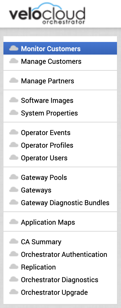
VeloCloud Orchestrator Operator Menu
Orchestrator (VCO).
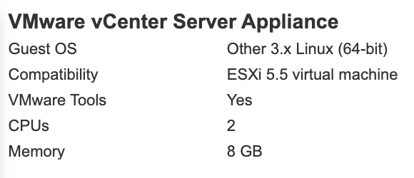
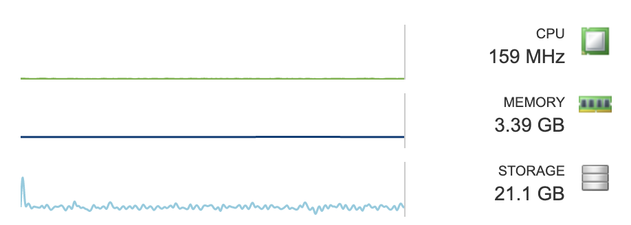
The VCO is the portal that is used to create, configure, and monitor VeloCloud SD-WANs. VeloCloud Orchestrator is multi-tenant and very powerful. Through a single Orchestator and its associated Gateways, one can create SD-WANs, or Software-defined Wide Area Networks, for Customers or Partners. A customer is able to manage and monitor their own VeloCloud Edges, Network Profiles, Business Policies, Firewall Rules, and more through the VCO. Partners are able to create their own customers within the VCO and manage their customer environments directly. The VCO is also used to activate and configure Edges. The VCO is a virtual machine that can run on vSphere, KVM, or AWS.
Gateway.
A VeloCloud Gateway, or VCG, is the device that an Edge routes traffic through when the traffic is defined to take a “multi-path” route (there will be more on route types in a future blog) or for non-VeloCloud VPNs. There are two main types of configurations for a Gateway, default and Partner. In the VCO, the VeloCloud Operator creates one or more Gateway pools and then places Gateways into that pool. Gateways are virtual machines that can run on vSphere, KVM, or AWS.
Gateway Pools are then assigned to Partners and/or Customers.
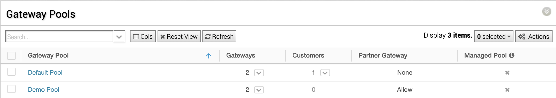
VCO Gateway Pools

VCO Customers
In a Cloud Hosted Model where Gateways are in default mode, an Edge is assigned a primary and secondary Gateway based on Geo location through the Maxmind database. The Edge’s peered Gateways are geographically closest to that Edge. The Edge device sends all “multi-path” traffic to its primary VCG and the Gateway then sends the traffic on to the intended destination. Return traffic is sent to the Gateway and then back to the Edge device. If the Edge identifies one of its Gateways as unreachable after 60 seconds, it marks the routes as stale. If the VCG is still unavailable after another 60 seconds, the Edge removes the routes for this Gateway. If all gateways are down, the routes are retained, and the timer is restarted. If the Gateways reconnect, the routes are refreshed on the Edge.
An SD-WAN with Partner Gateways gives the Operator the ability to route traffic to specific VCGs from Edges based on subnet. This is a value-add beyond the Cloud Hosted Model. A Partner will place Gateways geographically close to the services that they offer. When an Edge peered with a Partner VCG wants to access that service, the Edge leverages the tunnel to the Partner Gateway assigned for that service by subnet. Often Edges that are peered with partner Gateways have an average of 4 Gateways manually assigned. This number generally equals the number and locations of the services that the Partner is providing the customer such as SaaS offerings, Cloud services, etc.
You can see in the screenshot below that I checked the box for Partner Gateway during the Gateway creation and was given an option to define which subnets should be routed by that Gateway.

It is important to note that VCGs do not talk to each other and are not aware of each other’s state. Traffic is not routed between Gateways. The Edge sends “multi-path” traffic to its Gateway, that traffic is sent to its destination. When the destination responds, it is routed back through the Gateway to the Edge.
Gateways can be assigned to multiple Gateway Pools. Gateway Pools can be assigned to multiple Customers and Partners within the VCO. Partner Gateways should be placed closest (within 5-10 ms latency) to services that the Edges will access. Default Gateways should be geographically close to the Edges deployed in the Customer SD-WAN. It is not ideal for an Edge on the west coast of the US to send traffic to a Gateway on the east coast of the US before it is routed to its destination, for example.
Edge.
VeloCloud Edge, or VCE, devices are where the magic happens! Edge devices can be physical or virtual. They are implemented in enterprise datacenters, remote locations, and hyperscalers. Edge devices are able to aggregate multiple WAN links from different providers and send traffic on a per packet basis through the best WAN link to its peered Gateway. An Edge can aggregate the multiple WAN links and remediate issues found on public Internet providers such as loss, jitter, and latency. Even if just one WAN Link is connected to a VCE, improvement can be seen because of remediation capabilities of the Edge device.
In this screenshot you can see that VoIP traffic quality was greatly improved by the VCE. This VCE only has one WAN link.

VeloCloud Voice Enhancements
All VCE Management is performed via the VCO in the customer portal. The Enterprise Administrator uses Profiles to manage Edge devices. This makes it very easy for thousands of VCEs to be managed with the modification of a single profile. Enterprise Administrators can also override the profile settings to give individual VCEs a unique configuration that is necessary for it specific site.
Edges can be configured in three main functions. As a default VCE, a Hub, or Internet Backhaul. The default VCE routes traffic as described above leveraging its profile rules and Business Policies. It might connect to a Hub or Internet Backhaul. A Hub is when one or more VCEs act as a central location for other VCEs to connect over VPN. A Hub is generally created at major data centers. An Internet Backhaul is a destination for traffic is routed via Business Policy rules from VCEs back to a single location such as a data center. This is often used for security or compliance purposes. I will provide more information on Business Policies in a future blog.
VCEs are created within the VCO by the Enterprise Administrator and assigned a profile. This profile includes all configuration items for interfaces, Wi-fi, static routes, firewall rules, business policies, VPNs, security services, and more. When the VCE is activated by the VCO, all configuration is pushed to the VCE by the VCO, and the VCE is peered with its primary and secondary gateway and Partner VCGs, if any.
Once the VCE is online, the VCO displays data about the traffic type, source, destination, and quality that passes through each VCE. A world map is displayed that shows all VCE locations and their status in the customer portal.

VCE Monitoring. Applications Tab.
There are three ways that the VCE will route traffic. The way that traffic is routed is determined by Business Policies in the Edge Profile. These three routing types are defined as Network Services. They are Multi-Path, Direct, and Internet Backhaul. Multi-Path means that the VCE determines the best carrier for each packet from all WAN links. Each packet is routed to a Cloud or Partner Gateway. Direct is when the Enterprise Administrator routes specific application traffic by defining a single WAN link and does not route through a VCG. Internet Backhaul is described above.
The VeloCloud platform is extremely robust and easy to use at the same time. The ability to configure VCEs and provide security and services to 1000s of sites with a few clicks is nothing short of amazing. If you are looking to improve WAN quality, move away from expensive MPLS, aggregate multiple WAN links, create VPNs across the enterprise, provide security services, and have an easy to use portal to accomplish it all, definitely look at VeloCloud.
Thank you for reading! I will provide details on how to deploy and configure VCO, VCGs, and VCEs in the next blog of this series.
I want to give a shoutout to Cliff Lane at VMware for spending a lot of time answering my numerous questions about how VeloCloud works. Without him, this post would not be possible (or at least correct)! Thanks Cliff!