Configuring Ubiquiti Unifi Gear for Starlink
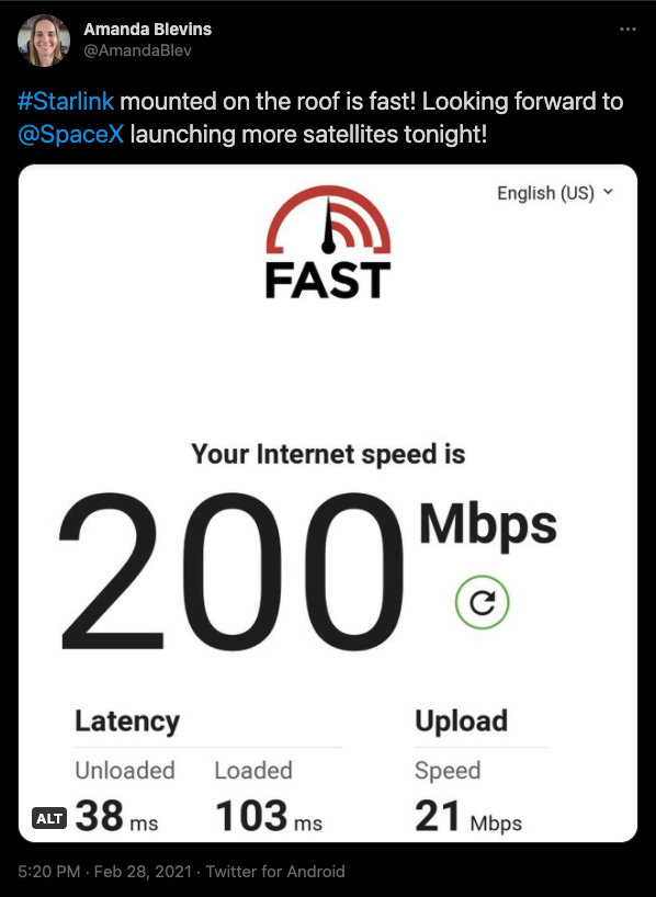
My tweet showing 200 Mbps download speed while testing my dmark cable.
After thawing out from the Starlink dish install with my brother-in-law, sending in the support ticket about the mount (that I still have not received a reply to), and investigating dinner options, I sat down on the couch with my laptop to figure out how I was going to leverage the Starlink uplink to meet my user experience requirements. The first step was to make sure that my dmark work was successful. I went downstairs to the gear closet, powered up the Starlink PoE injector and router and ran another speed test on my phone. 200 Mbps down! I’d say my home wiring was working just fine. I unplugged the ethernet from the Starlink router and plugged it into WAN2 on the Ubiquiti Unifi Secure Gateway (USG) PRO 4 and headed back upstairs. An important note: if you are not using the Starlink WIFI router, you can no longer see any information or stats about your Starlink connection. No more debug stats or other useful insight. I don’t know if this affects things like service upgrades or data collection for SpaceX. But, I was not interested in having a double NAT setup that might impact user experience.

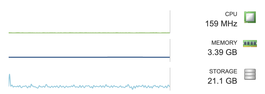
Ubiquiti Unifi Controller ISP Load Screenshot. The large throughput usage spike is during an ESO raid (ESO is Elder Scrolls Online. A raid is a run with 12 people to beat a Trial).
If you are responsible for your household’s connectivity to the outside world like me, you know how any blip in service can result in a crisis. We’ve been getting by with 26 Mbps down and 6 Mbps up on point-to-point WIFI for most of the pandemic. However, when my home users are pushing the limits of my service and my Internet Service Provider (ISP) is loaded with users at the end of the day, gaming is almost impossible. I’ve pulled out my hotspot so I don’t lag out during a raid and cause a group wipe. I’ve been extremely impressed with Zoom working well in the worst of internet connectivity. I can’t say the same for Teams or Google Meet. There’s plenty of calls I’m on where I don’t see anyone’s video on those platforms. I assume this is how they deal with my poor connectivity.
This blog outlines my design that I’ve implemented to maximize my home’s user experience. As with any design, yours should align to the requirements you have. The other people in my household use the internet mainly for streaming Netflix, YouTube TV, Hulu, and Amazon Prime. They also have the occasional telehealth or fun virtual gathering. There’s definitely a lot of web browsing, social media, and messaging platforms use. My user profile is that of any home worker plus online gaming requiring real time inputs. I don’t stream due to many factors, but mostly because of my internet speeds. I do record my screen and audio locally to review the runs, and I log the raids which increases the work my client does, but it doesn’t seem to be a major factor when considering the connectivity requirements. Maybe one day with Starlink I will be able to stream!
My rural ISP and Starlink have the same latency, 40-60 ms. This is completely satisfactory for online gaming unless you’re a professional esports athlete, then I wouldn’t recommend it. I’d probably sit in the data center with a cross-connect to the cage where the game is hosted if that was my job! However, the biggest issue with Starlink right now is that I only have about 73% coverage. And I experience a 30 second disconnect every 15-20 minutes during the day. How do I know I have 73% coverage? There are a number of sites with Starlink maps and other Open Source projects. Satellite Map Space and Starlink Coverage in GitHub are the two I have seen.
Clearly, 30 second disconnects multiple times an hour does not work for online meetings and gaming. Therefore, Starlink cannot be my internet connection for those activities. But I really want to have the much faster upload and download speeds for everything else! Based on the rest of the household’s user profile, the majority of their activities can handle those disconnects. Plus, if all of that traffic is removed from the rural ISP connection, it frees up bandwidth and lowers latency. My plan was to route all traffic except for meetings, virtual gatherings, telehealth, and online gaming over Starlink.

Screenshot from the Unifi Secure Gateway Details page. The IP Address has been removed from the image.
Enabling Starlink on WAN2 on the Unifi USG PRO 4 was easy. Navigate in the UniFi Controller to Settings -> Create New Network. Label the link for WAN2, enable Failover only, accept the rest of the defaults, and Save. After that, I was able to see that WAN2 received a Starlink IP address and traffic was moving over the link. Things were moving quickly and easily. Red flag! The pain started as I was clicking around the Unifi Controller GUI to figure out how to route my different subnets over WAN1 or WAN2 based on my preference aligned to the user experience requirements. This is called Policy Based Routing (PBR). After Googling I found that configuring PBR is not an option in the GUI and it must be configured via a JSON file stored on the controller. I also noted the irony that I only learn about and configure Policy Based Routing on Sundays from the couch. The last time was for a VMworld demo!
Most of my Googling resulted in reading about people’s disappointment that PBR was not in the GUI. The complaints on the Ubiquiti forums began years ago. Rather than including the capability in the GUI, Ubiquiti wrote a Support and Help article on how to configure PRB through the Unifi Secure Gateway interface and JSON.
After reading the above article and the related article about USG Advanced Configuration with JSON multiple times, Googling more to see if people posted their JSONs for PBR, and sighing loudly, I went to work. I have multiple subnets for various purposes in my house. But none of VLANs were for users I wanted to give uninterrupted internet access to (since this is usually a given). The first step was to create a new network in the Unifi Controller GUI. I also created a WIFI SSID for the new VLAN to enable easier testing since I wasn’t near an ethernet port. The first test of my capabilities was to route the new VLAN over WAN2.
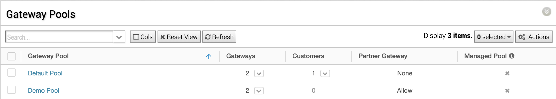
I am not a fan of static routes. They feel lazy (Like GOTO statements in BASIC. Clearly my elementary school coding experience was traumatic.) and should only be used as a last resort. Instead, I wanted to properly configure failover groups between my two uplinks and designate a primary route for my VLANs based on user requirements. I also wanted to use pointers to groups of VLANs rather than having to explicitly define subnets, but from what I could find, subnets must be explicitly defined in JSON Policy Based Routing. Working with what I was given, I opened an SSH session to my USG and started typing. This part was straight-forward. I scrolled to the “Routing Traffic to Different Load Balancing Groups Based on the Source Network” part of the Policy Based Routing help article, substituted in my subnet for the session state VLAN, and typed the commands into my USG. I connected my phone to the newly created WIFI SSID and ran a speed test. 110 Mbps down. Success!
If you don’t want to navigate to the Unifi help article at this time, here is a copy paste of the example code to run directly on your USG:
configure
set load-balance group wan2_failover interface eth2 failover-only
set load-balance group wan2_failover interface eth3
set firewall modify LOAD_BALANCE rule 2503 action modify
set firewall modify LOAD_BALANCE rule 2503 modify lb-group wan2_failover
set firewall modify LOAD_BALANCE rule 2503 source address 192.168.1.0/24
commit ; exit
Note: eth2 is WAN1 and eth3 is WAN2 on the USG PRO 4. Use the show interface command when connected via SSH in your USG to verify which ethernet interface are your WAN ports.
Second note: if you are curious why we couldn’t stop here, whenever the USG reboots, any configuration applied in the command line interface is erased. This is why we need the custom JSON file stored on the controller. The controller applies the configuration from the JSON upon a provisioning event.
According to the help article, the next step is dumping the USG config to a text file and using this text file to populate the JSON on the controller. This is where the fun really began. Here’s why:
1. I force myself to use Linux without a GUI at home to improve my skills. Generally, doing anything requires learning something new on Linux first.
2. JSON is not fun.
3. Editing JSON in Nano is really not fun.
The Ubiquiti article mentioned above goes into detail on creating and using the config.gateway.json file. If you copy and paste the entire config dump on the USG into your config.gateway.json file, you can no longer control your Unifi setup through the controller. With my obvious Windows background and preference for a GUI, this was a no go for me. Therefore, I had to delete everything from the JSON file that the USG created except for the areas that the above commands generated for my Policy Based Routing. Also, I had to keep track of all the {s and }s and still retain the section headers for the JSON to work.
In an effort to avoid all of this editing, I Googled some more to find any JSON file posted that already accomplished what I wanted to do. Unfortunately, those examples used static routes rather than load balancing. The one example I found that did use load balancing wasn’t valid even though it was a valid JSON file. More on this later.
So, back to Nano over SSH. You can see my true procrastination personality here! After avoiding editing by Googling, then editing, and counting brackets, I was ready to apply my new JSON configuration that would accomplish (hopefully) what the six simple commands above did. Spoiler alert: It didn’t.
To apply the new JSON file, there are two steps.
1. Restart the unifi service on the controller machine. In Ubuntu the command is
sudo service unifi restart
Note: if this takes you as many tries as it does me, press the up arrow a few times and enter to restart your service.
2. Navigate into the Unifi Controller and force provision to the USG under Devices -> USG -> Config -> Manage Device -> Provision (or trigger this from the USG CLI).
If your Unifi Controller is pushing an invalid JSON file to your USG, you’ll notice your USG is stuck in the provisioning phase. The only way to stop this is to delete or rename your json file and the provisioning phase will complete successfully. Most times, the USG will reboot after this. The result of the USG reboot is the internet is unavailable, and it will elicit a loud huff from anyone trying to watch YouTube TV while you curse at your screen. There are many ways to ensure your JSON file is valid. Since I was using my high-tech Nano editor, I preferred a SaaS solution rather than wrestle with Linux to install a development tool. This site is recommended by Ubiquiti: https://jsonlint.com/
After the dreaded USG reboot and subsequent cursing, I pasted my json file into the SaaS verification tool. I was missing curly brackets. I added those in, hoped all my commas were right, restarted the service, and forced a provision. Still stuck in provisioning.
I reviewed the one JSON example for a similar load balancer setup that I found online. I edited my file to match that format (which the author said was verified by a JSON validator) and pasted my file into the JSON verification tool on the site above. It did return that the JSON was valid. When I force provisioned this version of the config file, the USG was still stuck in provisioning in the Unifi Controller. Then I started reading about USG error logs.
One person online was of the opinion that verbose / debug logging had to be enabled to troubleshoot JSON config issues. That sounded like a lot of work, so I kept Googling. Another person suggested connecting via SSH to the USG and run
tail -f /var/log/messages
That I was down for! Even though the USG is in a provisioning state, you are able to SSH to it and run commands if you weren’t already connected. My tail -f command flooded my terminal window with error messages that hurt my brain to decrypt. Googling these messages provided no insight. So, I stared at them longer. Finally, I figured out what was happening. Even though the JSON file was valid according to the JSON verification tool and copied from a forum post of someone who was quite confident in their JSON abilities, it was wrong. It needed another set of curly brackets because the USG was interpreting my load balancer rules as an entry under the firewall section! @#*($%&*(^%*(@#!!!
Back in Nano I counted curly brackets again, added in another set, moved around a comma or two, crossed my fingers, and copied and pasted it to the JSON verification tool. It told me it was valid. I restarted the service for the umpteenth time, force provisioned the USG, and threw up my arms with a victory cry after it provisioned successfully. I tested my download speeds on my phone that was connected to my special VLAN, sure enough, they were FAST. I tested the download speeds of my computer that was supposed to route through the rural ISP, sure enough, they were SLOW!

Feeling smug, I tweeted my success.
Then I thought, wait, I actually want all of my VLANs to route through WAN2 and fail to WAN1, and I want my special VLAN to route through WAN1 and fail to WAN2. You’re probably thinking, why not swap ports for the uplinks and call it a night? Well, I would, except my rural ISP authenticates by MAC address. If I swapped ports, I’d have no rural ISP connectivity because it sees a different MAC address. And it was 9 pm on Sunday - there isn’t anyone to answer the phone and make this change.
Therefore, I had to add more firewall rules to my oh so fragile JSON file. I didn’t want to create yet another network to test with, so I figured the guest network subnet could be the second one to move. Remember how I tested if I was my traffic was going out the correct uplink? Yes, a speed test. The difference between 8 Mbps and 150 Mbps is a pretty good test… or so I thought. Well, I forgot that I had setup a bandwidth restriction on the guest network subnet a month ago to prevent video uploads to YouTube from taking down my internet. I spent another 15 minutes of complete frustration and Googling to determine if Unifi Guest networks are compatible with Policy Based Routing. I couldn’t find information stating one way or another. I decided to go all in and added in a firewall rule for the subnet that all of my NVIDIA Shields are on. I braced myself for the fifth loud huff of the night as YouTube TV was interrupted. But, it never happened and that picture sure looked crisp running over Starlink!
It was only then that I remembered my bandwidth limit rule on the Guest network and went through the exercise of removing all references to it in the Unifi Controller GUI so I could delete it FOREVER! Once deleted, my speed test for the Guest network showed 80 Mbps. I guess that was fine with two NVIDIA Shields streaming and the Ubuntu updates downloading. Way better than the 6 Mbps download speed I enforced before. I made a few more changes to switch ports connected to RJ45 jacks in my office to use the special VLAN in preparation for work and leading a raid the next day and called it a night.
I know you’ve been waiting with bated breath to see my masterpiece of a JSON file so you can avoid everything you just read here. Ta da!
{
    "firewall": {
        "modify": {
            "LOAD_BALANCE": {
                "rule": {
                    "2606": {
                        "action": "modify",
                        "modify": {
                            "lb-group": "wan2_failover"
                        },
                        "source": {
                            "address": "10.10.0.0/16"
                        }
                    },
                    "2607": {
                        "action": "modify",
                        "modify": {
                            "lb-group": "wan2_failover"
                        },
                        "source": {
                            "address": "10.50.1.0/24"
                        }
                    }
                }
            }
        }
    },
    "load-balance": {
        "group": {
            "wan2_failover": {
                "flush-on-active": "disable",
                "interface": {
                    "eth2": {
                        "failover-only": "''"
                    },
                    "eth3": "''"
                },
                "lb-local": "enable",
                "lb-local-metric-change": "enable"
            }
        }
    }
}
Seems rather insignificant for all that work, huh? It could certainly be fancier to include rules around testing the connection and how many ping failures before initiating the failover. But, that requires working out some math considering how frequently the Starlink connection goes offline to prevent unnecessary failovers. With today’s and future SpaceX Starlink launches, my experience might change, so I just left it as it is.
Someone with far more patience than me might figure out IP address ranges and ports associated with Zoom, Team, Google Meet, Telehealth sites, Elder Scrolls Online, and everything else that needs a stable connection and have a much longer JSON than you see here which would forgo the need to manually change networks / SSIDs when I want to do something other than download and upload large files or stream content. But this works for me. And, I’m optimistic about Starlink improving their service quickly!